The MWI DD 1042/1242 frame tube is ASTM 500 grade C tubing or grade B to meet C specs.
DRUMS
Wide barrel design reduces line interference when running double fast line.MW Industries, Inc.s spool drum design reduces drumshaft flex and weight while increasing total strength.Tubing drum has 20 x 1 Lebus grooving with turn back and kick plates to reduce line wear and assist in spooling.
BRAKE SYSTEM
MW Industries, Inc. uses water-cooled main drum flanges, splash-cooled sand drum flanges, and Eaton water-cooled disc assist with emergency stop.MWI brake flanges are rolled, machined, built up (with submerged arc hard surfacing wire overlay), re-machined, and properly balanced to specifications to ensure long life and proper wear for asbestos brake pads.
DISC CLUTCH
3 3- 24 PO Style Power Grip Disc Plate Main Drum
2 2- 24 PO Style Power Grip Disc Plate Sand Drum
TTwin-Disc or W.P.T brand air clutch mounted outboard of drawworks frame and chain case mounted on lower output shaft.MWIs use of the chain clutch on the lower shaft reduces required clutch size, air requirements, and eliminates all live chains.
DISC ASSIST
EEaton three (3) - 24 water-cooled disc assist operated with variable pressure adjustment on operating console for proper speeds that allow safe and normal running job application.Disc assist is also equipped with a main drum emergency stop.
CHAIN DRIVES
DDrives or Diamond Hi-tensile Double 160 roller chain is oil bathed for a long life.The chains are fully enclosed in a one-piece, aluminum chain case with gasket flange.This design prevents case leakage due to warping.Inspection plates provide for chain maintenance and removal without removing the chain case.Output chain can be tightened by sliding right angle gear box.Main drum chain tension can be adjusted by a hard rubber surfaced idler bearing.
MWI 1042/1242 HD POWER DRIVE
For ease of replacement, MWI uses off-the-shelf bearings.The right angle drive unit has a gear ratio of 1:1.90.
OPERATORS CONSOLE
The operators console consists of clutch, engine throttle, air slip controls, assist brake control, and emergency shutdown.There is a transmission selector, emergency stop on main drum, tong retractor, start, stop, horn, and option of two (2) winch controls. The console is located behind the drawworks frame, in the mast base, for excellent drum visibility and operator comfort.
LUBRICATION
MWI uses remote bearing lubrication.Lubrication system ensures complete lubrication of drum bearings.Lubrication points are located conveniently, outside the drawworks frame, for ease of maintenance.
HOIST
Two (2) hydraulic planetary style winches are mounted on the rig deck.Capacity of the hoist is 8,000 lb. with 275 of ½ line with tail chain (line and chain extra).
TANKS
Drawworks comes complete with one (1) 350-gallon coolant tank for three (3) - 24 Eaton disc assist and circulating flanges on 12 x 42 main drum flanges.One (1) 250-gallon hydraulic tank is included.Both tanks are equipped with site glass and thermometer. Drawworks is completed with all covers on top and around drawworks.
DISC ASSIST AND TRANSMISSION PROTECTION FEATURES
This unit has Murphy switch gauges, in the run box, mounted on the deck. The run box provides a warning or engine shut down in the event that the transmission temperature rises above 275 degrees, the transmission pressure drops below 10 lb., or the Eaton disc brake temperature rises above 170 degrees F.
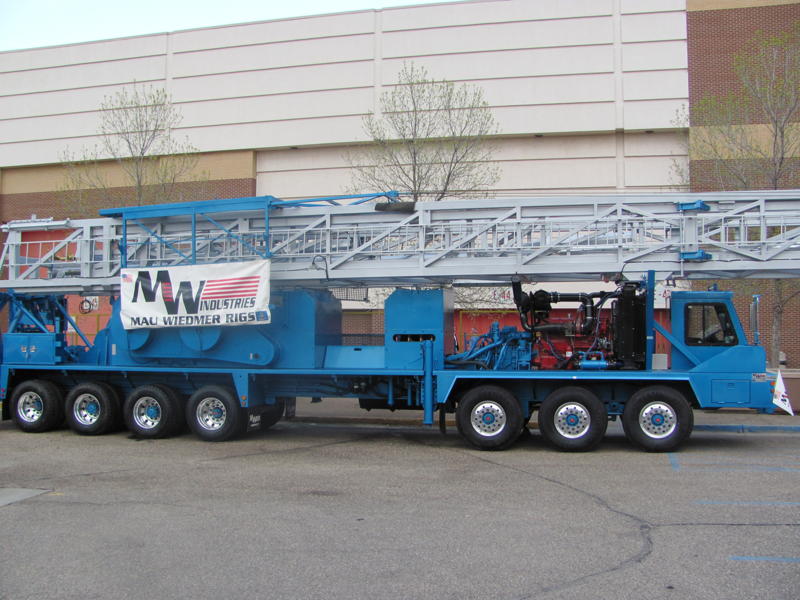
TELESCOPING MAST
OVERALL
A telescoping mast, with open face mast design, is manufactured to meet API-4F specifications PSL1.The open face design utilizes structural steel construction, which allows for maximum blockclearance.Mast includes a ladder from ground to crown and a block cradle with chain and hook for securing block during transport.
SPECIFICATIONS
Mast Height 104 (31.7 m)
Number of lines to block 4, 6 or 8
Capacity
4-Lines255,000 lb.
6-Lines275,000 lb.
8-Lines295,000 lb.
Drilling Line Size1 (25.4 mm)
Racking Board Height55 (16.76 m)
Racking Board Capacity
2 7/8 EUE24,140 (7357.9 m)
3 ½ Drill Pipe13,680 (4169.5 m)
4 ½ Drill Pipe6,480 (1975.1 m)
Rod Basket Height78 6 (23.9 m)
BASE SECTION
Four (4) leg style base section is hinged to carrier frame.Two (2) turnbuckles, attached from top of mast base to carrier frame, allow for mast angle adjustment.The well-side mast legs have manual screw jacks 18 from ground level for fast and safe rig-up conditions.Mast is set at 3.5 degrees.
MAST
600 Series includes the 104; 295,000 lb. 6x6 square tube mast.
CROWN BLOCK
McKissick roll forged crown sheaves are set up for a four (4), six (6), or eight (8) line string-up.Crown sheaves are grooved for 1.All sheaves are mounted on tapered roller bearings with grease zerks for ease of maintenance.
600 Series Crown includes: one (1) 30 (762 mm) fast line sheave, one (1) 30 (762 mm) dead line sheave, three (3) 24 (610 mm) crossover sheaves, and one (1) 24 (610 mm) sandline sheave for 9/16 cable.
RACKING BOARD AND ROD BASKET
The mast includes an all welded racking board.The racking board automatically deploys as the mast is extended.Racking board has been slowed down for larger pumping units.The mast includes an automatic deploying rod basket with rod hangers, air transfer system (on a roller trolley slide for easier access for placement in fingers), and safety chain with binder on end of fingers.
MAST RAISING SYSTEM
The mast utilizes two (2) 3-stage double acting raising rams and one (1) double-stage telescoping cylinder built with a slide.Load pins are hydraulically operated.Raising, telescoping, and load pin controls are located under the operators console for easy access and operation.Hydraulic pressure gauges are mounted on the mast base to provide system monitoring during the raising/lowering process.The hydraulic system incorporates a safety choke system to control flow to telescoping or raising cylinders in case of a hydraulic line rupture or damage.
GUYLINES
Mast includes two (2) ¾ bumper guys from the crown to carrier, four (4) 5/8 wind guys, two (2) 9/16 board guys and two (2) 3/8 floor lines from board to floor.
DEADLINE ANCHOR
Deadline anchor is designed and engineered to strict API specifications and rated for a 150,000 lb. maximum deadline load.The deadline anchor is located on the off-operators side of the rig floor and comes with a line clamp.
FOLDING WORK PLATFORM
Platform is constructed of rectangular tubing and is decked with a reduced slip grating.Platform is adjustable in height from 3 (0.91 m) to 9 (2.74 m) from ground level.Included is a sliding access door and safety railings.Optional telescoping staircase with safety rails available.
POWER PLANT and TRANSMISSION
ENGINE
MW Industries, Inc. offers the customer a CUMMINS QS X 15 Package; 485 horsepower, including Jake Brake.
TRANSMISSION
M 5610A Allison automatic transmission, with drop box, provides six (6) forward speeds and one (1) reverse.Remote shifting is provided from the operators console via an electronic shifting system.Rig mode provides 1st through 5th gears and road mode provides 1st through 6th gears.First gear override is incorporated through air slip control for quicker shifting on deeper well depths.Transmission uses a separate cooler, integrated into the radiator.All engine/transmission combinations are reviewed and approved by the transmission manufacturer for correct engineering, installation, and engine compatibility.MWIs design allows for the removal of transfer case independently.
SPECIFICATIONS
Net Input Torque (max.)1750 lb.-ft 2373 Nm
Torque Converter3476 lb.-ft 4713 Nm
Gear Ratios:
First4.00:1
Second2.68:1
Third2.01:1
Fourth1.35:1
Fifth 1.00:1
Sixth0.67:1
Reverse 1-5.15:1
AIR, ELECTRIC AND HYDRAULIC SYSTEMS
AIR SYSTEM
One (1) engine driven 37.4-cfm water cooled compressor pressurizing an air system plumbed in accordance with applicable DOT regulations and requirements. The air system consists of a wet, primary, secondary and auxiliary tanks. Check valves prevent accidental air pressure loss from system due to single line failure.Main airlines are plumbed with OEM style steel airlines and compression fittings rather than threaded pipe with Bendix Twin AD-9 Everflow with heater probe. (Alcohol pot optional).
ELECTRICAL SYSTEM
12-volt electrical system, consisting of one (1) 160 amp alternator, two (2) batteries, one (1) 12V high output starter and voltmeter.Batteries are located in a steel battery box mounted on the carrier deck.Jumper lugs are mounted on the outside of box for quicker access and safety of personnel.Location of box provides excellent access for maintenance and service.
TONG CIRCUIT
The tong circuit consists of a remote mounted pressure regulator and gauge easily accessed by the operator while standing at the brake handle.The tong circuit does not include hoses, couplings or tongs.
HYDRAULIC CIRCUIT
Thestandard hydraulic circuit has a piston pump (closed center hydraulic system) capable of 29-80 GPM at 2500 psi, based on engine RPM.It also has a (open center) gear pump driven off the back of the piston pump;which supplies only the tong circuit with 14-37.5 GPM at 2500 psi depending upon engine RPM.There is an option of using a gear pump (open center system) instead of using the standard piston pump (closed center system), but specs, valves and plumbing change.
The closed center hydraulic system has a priority circuit that enables a cooling pump and two (2) winches to be live at all times when the hydraulic pump is engaged.The hydraulic circuit is then split one (1) of two (2) ways to the rig up mode or a neutral state.The rig up mode is disabled when not selected for safety.The rig up mode consists of four (4) leveling jacks, two (2) raising rams, one (1) scoping cylinder and one (1) load pin cylinder.There are two (2) option outrigger cylinders.The raising rams, scoping cylinder and load pin cylinders have three (3) individual relief pressure capabilities.Optional block mounted hydraulic valves are available.
7-AXLE CARRIER (Long Wheel Base)
OVERALL
The carrier is manufactured by Kimble Chassis and is a heavy-duty 7-axle oilfield carrier with three (3) front steering axles, four (4) rear-driving axles, one (1) pusher, and one (1) tag axle.All frame members are coped and welded for superior strength and durability.The carrier is designed for maximum maneuverability, road clearance, and turning radius.Locations of axles are specifically engineered to distribute correct weight in proportion to front and rear axles.MWIs engineering team will contact the applicable DOT of state(s) or province(s) for proper weights and bridge laws.
SPECIFICATIONS
Weights will change with configuration of the customers choice of blocks, string-up, and rig options.
CARRIER FRAME
A 21 x 57 lb. beam manufactured by Kimble Chassis, specifically for MW Industries, Inc.Front and rear tow lugs are welded to the end of the frame rails for proper load distribution during towing.Carrier HD-Deck is fabricated with 11 gauge diamond deck plate with 2½ wrap around main deck rails to ensure long life and durability with no deck sag.
FRONT AXLES
The tandem front steering axle set is rated at 24,000 lb. per axle and spring suspension rated at 48,000 lb.
REAR DRIVING AXLES
Dana DD-463-P Tandem Series rear-driving axles are rated at 46,000 lb. Carrier includes Hendrickson walking beam rear suspension.Standard ratio is 6.17:1.
REAR TAG AND PUSHER AXLE
Rear tag and pusher axle are non-driving axles with air suspension.Brakes are rated for 22,000 lb. capacity.
BRAKE SYSTEM
16.5 x 6 ABS, with auto slack adjusters, DOT approved regulation antilock air brake system.Drum style brakes on all axles.Carrier is equipped with additional air emergency brake.
TIRES AND WHEELS
The four (4) front tires are 445/65 R22.5 wide-base tires mounted on 13 x 22.5 aluminum hub-piloted bud type wheel.The 16 rear tires are
11R 22.5 General or Continental all-terrain tires mounted on 8 x 22.5 hub-piloted aluminum bud style wheels.
CAB
MWI easy access cab is a custom made, soundproof, single person cab set up for left-hand drive.Cab is equipped with air suspension seat, heater, defroster, windshield wiper, windshield washer, air horn, electric windows, and West Coast mirrors with lights and heater.Instrumentation consists of speedometer, voltmeter, oil PSI with warning lights, tachometer with hour meter, coolant temperature with warning lights, air PSI, and fuel gauge with warning lights.Tilt and Telescopic steering.
STEERING
Rig steering is a hydraulic assisted system, with one (1) cylinder mounted on each axle and a hydraulic assisted steering box (carrier is equipped with wide turning radius).
RIG LEVELING SYSTEM
Rig leveling is done with four (4) MWI hydraulic leveling jacks with locks.Front jacks have 22 stroke of travel, rear 15.All jacks are controlled from the operators console.
OTHER EQUIPMENT
The MWI 7-axle carrier comes complete with integrated aluminum rig stairs, aluminum operator side fold-down walk ways, OSHA approved aluminum guardrails, aluminum driveline covers, one (1) tong retractor, two (2) locking tool boxes, and one (1) 100-gallon fuel tank.
STANDARD PAINT and PREPARATION
DUPONT COMMERCIAL COATINGS
PREPARATION
Rig is thoroughly washed and sandblasted prior to priming.
PRIMER COAT
MW Industries, Inc. uses a DuPont satin high solid epoxy primer, 3 mils thick.
TOP COAT
High gloss polyurethane, 2 mils thick.
Metallic and/or pearl optional, 2 mils thick.
CLEAR COAT
The unit is finish coated with up to two (2) non-metallic clear coats. Heavy-duty performance finish coat is DuPont 3-4 mils in thickness.
Options
*Complete tool package-rod equipment, tubing equipment, etc. *Hydraulic extended out-riggers with manual tail screws. *Lighting package *Cold package *Complete mast assembly *Rod flanges *Brake flanges *McKissick traveling blocks *Other options available upon request.